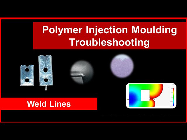
Weld lines are one of the most common defects found in injection molded plastic parts. When two flow fronts of the molten plastic converge in the mold, they may not fully fuse back together. The result is a visible line on the part called a weld line, which indicates a weak spot. As a professional plastic injection molding manufacturer, I will share 4 root causes of weld line defects and some solutions to prevent them.

Why Weld Lines Matter in Injection Molded Parts
At first glance, weld lines may seem like a purely cosmetic issue. But in reality, they negatively impact the strength and durability of injection molded components.
For example, plastic parts with weld line defects are more prone to cracking or breaking at those spots when placed under stress. This fragility poses safety issues for products like automotive parts or medical devices.
Additionally, weld lines distort the aesthetic appearance of items where surface finish is important. So they can reduce the commercial appeal of consumer goods like electronics cases or toy building blocks.
Clearly, weld lines present functional and economic consequences that manufacturers cannot ignore. Let’s examine what causes them during the injection molding process.
What Causes Weld Lines in Injection Molding? 4 Root Causes
While executing injection molding runs, plastic flow fronts can separate and rejoin in several situations:
1. Obstacles in the Mold Cavity
Holes, edges, inserts, and other obstructions in the mold tooling divert the flow of molten plastic into two or more paths temporarily. As the flows reconnect along the rear side of the obstacle, inadequate temperature or pressure prevents them from blending back into one homogeneous melt.
Core pins used to create internal openings like holes or threads are common causes of weld lines. Another example is side-action cams and slides that retract during injection then extend into the mold cavity prior to solidification.
2. Multi-Cavity Molds
Molds containing two or more separate cavities with dedicated gate points inherently split the injection pressure. This divided flow converges somewhere within the runner system en route to the cavities. The merging location tends to produce recurrent weld lines part-to-part.
While minimizing gates can help, most multi-cavity molds will exhibit weld lines to some degree. Savvy mold makers will attempt to locate them in subtle, non-critical areas during design.
3. Uneven Wall Stock
Where plastic parts incorporate both thick and thin-walled sections, the melt fronts flowing through these areas solidify at different rates. The slower thick-wall flow and faster thin-wall flow ultimately come together downstream, potentially failing to unify properly.
Sudden transitions in wall stock act as flow obstructions themselves, bifurcating the melt stream until it reconnects along the rear side. Gradually tapering any thickness changes allows a more even flow convergence with reduced weld line risk.
4. Improper Venting
Trapped gases present another barrier to reconciling two melt flow fronts in the mold cavity. Without adequate venting, pockets of air get compressed between the converging flows rather than escaping the mold tooling.
This causes a localized hot spot from the gas rapidly compacting. In extreme cases, the spiked temperature degrades the plastic polymer, leaving a telltale black or brown burn mark. More benign cases with modest air entrapment still interrupt proper fusion between the flow layers, resulting in a hairline weld defect.
How to Prevent Injection Molding Weld Lines
Ideally, parts should be designed to avoid flow obstructions and perturbations altogether. But for most commercial items, some irregularities are unavoidable.
Fortunately, adjustments to the mold tooling and optimized processing parameters can minimize weld line occurrences:
- Increase injection fill velocity to deliver hotter melt fronts for better flow welding.
- Boost injection pressure to enhance turbulent flow mixing of the converging fronts.
- Raise barrel temperatures to reduce viscosity and improve melt fusion ability.
- Relocate gate positions to change weld defect areas on parts.
- Add vents, increase clearances, and improve air evacuation paths in problem mold areas.
- Use hot runner systems to maintain higher melt temperatures throughout cavity fills.
- Standardize wall stock variations between thick and thin sections.
- Lower peak injection pressure gradually with a velocity/pressure transfer setting.
- Increase mold temperature to slow cooling and extend flow fusion time.
While tiny weld lines may persist in some injection molded components after implementing these fixes, the goal is to control their size and location. This circumvents any major weaknesses or visual defects.
Careful inspection of pre-production samples provides valuable feedback to hone in optimal process settings and material delivery control. This dialing-in reduces weld line prevalence prior to formal production runs.
Conclusion
In review, weld lines appear wherever two flow fronts fail to recombine during cavity filling in injection molding. Common causes include mold obstructions, multi-point gates, uneven walls, and poor venting.
While small weld defects only mar aesthetics, major ones compromise part strength and function at those spots. Carefully engineered molds and refined processing parameters minimize problematic flow separations. This yields more consistent, defect-free plastic components.
What do you think causes the most weld line issues in your injection molding applications? Are visual defects or functional impacts more concerning? Share your experiences and thoughts below!
