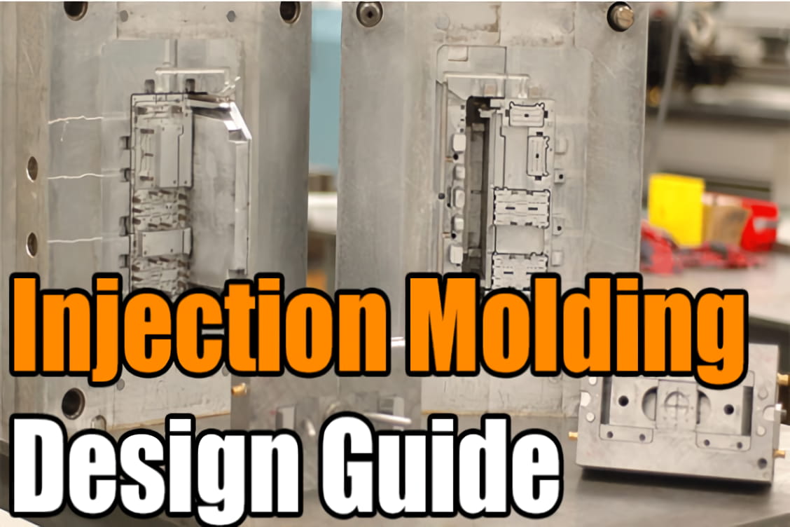
Injection molding is a common manufacturing process used to produce plastic parts at scale. Properly designing parts for injection molding is critical for avoiding defects, controlling costs, and achieving the desired appearance and performance. This comprehensive design guide outlines key considerations across part geometry, material selection, tooling, and secondary operations to optimize injection molded components.

Injection Molding Design Guide
Critical Design Elements
There are several critical elements to account for when designing parts for injection molding:
Parting Lines
The parting line is where the two halves of an injection mold meet to eject the cooled, solidified part. Parting lines will always be visible on finished parts to some degree based on location, draft angles allowed, and surface finishes. Strategically placing parting lines can help minimize visibility.
Undercuts
Undercuts refer to part geometries that overhang or cause an interference such that the part cannot eject cleanly from a simple two-part injection mold. Common examples include cross-holes, threads, and snap-fit hooks. Undercuts increase tooling complexity and costs. Where possible, parts should be designed to avoid undercuts using techniques like draft angles or reshaping features. Unavoidable undercuts can be accommodated through use of side-action cores and other inserts.
Draft Angles
Draft angles are essential on all vertical faces of a part to reduce friction and enable clean ejection from the mold. A minimum draft angle of 1-2 degrees is recommended for most features, with more being required for taller geometries or textured surface finishes.
Wall Thickness
Uniform wall thickness throughout a part is optimal to aid material flow, reduce warpage risks, minimize cycle times, and lower costs. Typical wall thickness specifications range from 0.060 to 0.180 inches depending on the material used. Gradual transitions should connect any sections with varying wall thicknesses.
Radii and Corners
Sharp corners concentrate stresses and cause earlier part failures. generous fillets and radii should be applied to all inside and outside corners where possible to maintain strength.
Advanced Design Considerations
In addition to basic geometry and draft requirements, the following features provide additional part functionality and require extra design diligence:
Bosses
Bosses serve as attachment points for inserts or self-tapping screws. Thin ribs or gussets should connect bosses to main walls whenever possible to improve stability and avoid sink marks from material shrinking.
Ribs
Ribs reinforce parts without increasing wall thickness. Ribs should be designed in accordance with wall thickness limits and incorporate fillets at their base to avoid stress concentrations.
Snap Fits
Snap fits enable assembly of injection molded parts without fasteners. Like other projections from nominal wall geometry, draft is essential on snap fit vertical walls to enable demolding. Thickness relative to nominal wall and placement require additional analysis when designing snap fit hooks or cantilevers.
Living Hinges
Living hinges act as thin, flexible connections between rigid plastic segments. Material selection is critical, with polypropylene and polyethylene common choices for consumer products. Hinge thickness, length limits, and inclusion of shoulders influence durability over expected life cycles.
Material Considerations
Material selection influences part appearance, performance requirements, tooling options, and manufacturing processes required. Some key plastic alternatives include:
- Polypropylene (PP) – Low cost resin with good chemical resistance often use for consumer products and piping
- Acrylonitrile Butadiene Styrene (ABS) – Common choice when higher strength and ductility are needed relative to PP. Used across automotive and electronics enclosures
- Polycarbonate – Optically clear high-strength option when impact resistance and dimensional stability are critical
- Polyamide (Nylon) – Preferred for mechanical parts needing higher strength, fatigue and wear performance
Surface Finishes
Different aesthetic looks and feels can be achieved on injection molded part surfaces depending on mold pre-treatment and textures transferred. Common alternatives per SPI standards include:
- SPI-A2 – Glossy, mirror-like finish achieved through mold diamond buffing
- SPI-B1 – Satin matte finish from using 600 grit sandpaper on mold
- Mold Texturing – Custom grain-like finishes applied through media blasting molds
Secondary Operations
Post-molding steps like assembly, labeling, printing, welding, or machining can extend part functionality as needed:
- Pad Printing – Method for adding color logos, labels, and graphics onto curved injection molded surfaces
- Ultrasonic Welding – Fuses separate molded components together by inducing high-frequency vibrations
- CNC Machining – Enables higher precision features difficult to integrate molded designs directly
Quick Design Checklist
When finalizing injection molded part designs, the followingchecklist covers key elements to review:
- Uniform wall thickness from 0.060 to 0.180 inches
- Minimum draft angle of 1 degree applied to all vertical faces
- Radii on all interior and exterior corners
- Supporting ribs added to isolated bosses
- Gussets connecting projected ribs back to nominal walls
- Gate, ejector pin, vent locations inspected
- Undercuts eliminated where possible
- SPI standard surface finish specified
Properly accounting for these critical design considerations will ensure dimensionally accurate parts with lower manufacturing defects and costs. Reach out with any questions on optimizing your next injection molded component or assembly.
